


How to Add LED Lights to NES Controllers
Transforming your NES controller with LED lights is a simple way to combine retro gaming charm with a modern glow. This guide explains how to install LEDs to light up buttons, logos, or the entire faceplate. All you need are basic tools, soldering skills, and a bit of patience. Here's a quick overview:
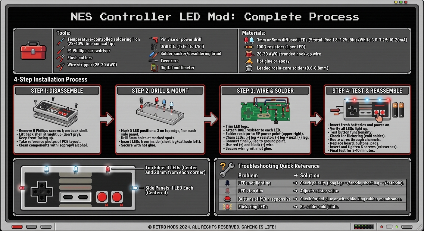
- Tools Needed: Soldering iron, Phillips screwdriver, wire cutters, and a drill.
- Materials: 3 mm or 5 mm LEDs, 100Ω resistors, 26–30 AWG wire, and hot glue.
-
Steps:
- Open the controller by removing six screws.
- Drill holes for LEDs in chosen spots.
- Solder LEDs with resistors to the 5V and ground points on the circuit board.
- Test the setup before reassembling the controller.
Step-by-Step Guide to Installing LED Lights in NES Controllers
NES Controller LED Mod - Let's Put an LED Inside!
Tools and Materials You'll Need
Before diving into your NES controller LED mod, gather everything you'll need to make the process smooth and efficient. Below, you'll find a breakdown of the essential tools, components, and workspace setup to ensure success.
Basic Tools
The most critical tool for this project is a temperature-controlled soldering iron. Aim for one rated between 25–40W with a fine conical tip, perfect for the small pads on the NES circuit board. Pair it with leaded rosin-core solder, ideally 0.6–0.8 mm in diameter, as it’s easier to work with and produces cleaner joints - great for beginners.
You'll also need a #1 Phillips screwdriver that fits snugly to avoid damaging screws. For cutting and stripping wires, grab flush cutters and a wire stripper designed for 26–30 AWG wire. If you're mounting LEDs, a pin vise or power drill with 1/16" to 1/8" bits will help create the right-sized holes for 3 mm or 5 mm LEDs. A solder sucker or desoldering braid is handy for fixing mistakes, while tweezers make handling tiny components much easier.
Parts and Components
For the LED mod, you'll need 3 mm or 5 mm diffused LEDs in your chosen color. Red LEDs typically have a forward voltage of 1.8–2.2V, while blue and white LEDs require 3.0–3.2V, all operating at 10–20 mA. Diffused LEDs are ideal because they provide even illumination. To prevent overheating, pair each LED with a 100Ω resistor when using the NES's 5V supply.
For wiring, use 26–30 AWG stranded hook-up wire - it's flexible enough to fit into tight spaces without stressing solder joints. Secure your components with hot glue or epoxy to keep everything in place. If you're looking for NES-specific parts or themed accessories, check out BJ's Game Vault (https://bjsgamevault.com), which specializes in retro gaming components. This can be particularly useful if you’re customizing a controller to match themed consoles or reproduction cartridges.
Setting Up Your Workspace
A well-prepped workspace is key to a smooth modification process. Use a stable, flat surface covered with a heat-resistant mat or silicone soldering pad to protect your work area. An adjustable desk lamp will help illuminate the fine details, while proper ventilation is crucial for dissipating fumes and dust. Avoid working on carpeted areas, and always ground yourself by touching a metal object before handling the circuit board to prevent static discharge.
Organize small parts in trays or magnetic bowls to keep them from getting lost. Snap reference photos of the controller’s internals before you start; these will help you reassemble everything correctly. Finally, keep a digital multimeter nearby to check 5V and ground points, verify LED polarity, and troubleshoot connections before sealing everything up.
Taking Apart the NES Controller
Opening the Controller Shell
The NES controller is secured with 6 small Phillips screws on the back shell. To avoid damaging the screws, use a #1 or #0 Phillips screwdriver that fits snugly into the screw heads. Carefully remove all six screws and store them in a safe place - losing even one can make reassembly more challenging.
Once the screws are out, gently lift the back shell straight up. Don’t pry or force it open. If you feel any resistance, double-check that all screws have been removed. Avoid using metal tools along the seam, as the older plastic can be fragile and prone to cracking or scuffing.
When removing the back, keep the front half of the controller facing upward. The D-pad, A/B buttons, and Start/Select buttons are loose components and could fall out. Removing the back shell will expose the PCB (circuit board), rubber button pads, and plastic button caps housed in the front shell.
Before moving forward, take a moment to organize and prepare the internal components for the next steps.
Preparing the Inside Components
With the controller open, take a quick reference photo of the PCB layout, cable routing, and button placements. This will make reassembly much easier later. When handling the PCB, lift it by its edges to avoid putting stress on the wires or solder joints. Place the rubber pads and buttons aside, keeping them in order.
Now, it’s time to clean the components. Wash the plastic shells in warm water with a bit of mild dish soap. Use a soft cloth or cotton swabs to wipe down the rubber pads, and clean the PCB contacts with isopropyl alcohol (70–99%) applied to a cotton swab. Make sure everything is completely dry before continuing.
If you're adding LEDs, test-fit them in the shell to find mounting spots that won’t interfere with the PCB or the button mechanisms. In some cases, you might need to trim small internal plastic posts using flush cutters or a hobby knife to make room for the LED wiring. However, avoid cutting any structural posts or screw towers needed for reassembly. Work in a well-lit space and at room temperature to ensure the materials and adhesives behave as expected.
Installing and Connecting the LEDs
Drilling Holes and Mounting the LEDs
Start by deciding where to place your LEDs. You'll need 5 in total: 3 along the top edge and 1 on each side panel. For the top edge, locate the center point and mark 20 mm (0.79 inches) from each corner. On the side panels, mark the center point of each.
Using a 3 mm drill bit, carefully drill holes at the marked spots. Apply steady pressure to avoid cracking the plastic. Once the holes are ready, insert each LED from the inside, making sure the short leg (negative/cathode) is always positioned on the left side. Secure the LEDs in place with hot glue to prevent movement during soldering and reassembly.
Once mounted, you're ready to wire the LEDs.
Connecting LEDs to the Circuit Board
With the LEDs firmly in place, it’s time to wire them. Start by trimming the legs of each LED to a manageable length. Attach a 100-ohm resistor to each LED to regulate the current. Solder the resistor to the 5V power point located at the upper right corner of the controller board. This spot conveniently connects the 5V+ and ground points via a copper trace.
Now, chain the LEDs together. Solder the positive leg (the longer one) of the first LED to the resistor. Then, connect the negative leg of that LED to the positive leg of the next one. Repeat this process until all LEDs are linked. To complete the circuit, solder a short wire from the negative leg of the last LED to the ground point near the 5V power feed.
Use red wires for positive connections and black wires for negative ones to keep things clear. Apply flux to ensure smooth soldering, and work carefully to avoid damaging the delicate metal traces. Once the wiring is complete, secure it with hot glue. Test the setup by installing batteries and touching the switch wires together. If all LEDs light up as expected, you're good to go.
sbb-itb-9a4764e
Testing and Fixing Problems
Checking LED Operation
Before you put your NES controller back together, it’s important to test everything while the shell is still open. Start by inserting fresh batteries and powering up the circuit. Depending on your setup, you can do this by pressing the activation button or briefly connecting the switch wires if you haven’t installed a tactile switch yet. Once powered, all the modified LEDs should light up right away. If you’ve added a tactile switch (often mapped to button A), press it multiple times to ensure the LEDs consistently turn on and off as expected.
While the LEDs are on, gently move the cable and tap the board to check for any loose connections. If an LED flickers or dims during this process, it could point to a cold solder joint that needs to be fixed. To make troubleshooting easier down the road, take clear photos of your wiring from several angles before closing up the controller.
Also, test every original button to confirm that the LED mod hasn’t interfered with their functionality. If any button feels mushy or doesn’t respond properly, address the issue now before sealing the shell. Should any problems crop up during testing, the following tips can help you identify and fix common issues.
Fixing Common Problems
If some LEDs aren’t lighting up while others are working fine, the first thing to check is polarity. Each LED has a long leg (the anode) that should connect to the positive circuit path, while the short leg (the cathode) connects to ground. If you find any LEDs with reversed polarity, unsolder them and correct their orientation. To confirm that an LED isn’t defective, you can test it by briefly touching its leads to a 3V coin cell battery with a resistor in series.
For LEDs that seem too dim, double-check the resistor value you’re using. Adjusting the resistor can help achieve the right brightness level. If you notice buttons feeling stiff or not working properly after the mod, partially reassemble the controller and inspect for any hot glue or wires that might be blocking the rubber button membranes. Clear out any debris using compressed air and ensure the rubber connectors are properly aligned with their pads.
Once you’ve worked through all these checks and fixes, you’re ready to reassemble the controller and enjoy your handiwork.
Putting the Controller Back Together
Reassembly Steps
Once you've confirmed everything is working as it should, it's time to put the controller back together. Start by fitting the circuit board back into its original spot in the front shell. Make sure the cable follows the strain-relief channel exactly as it did when it came from the factory. This ensures everything stays in place and functions properly. Next, place the D-pad, A/B buttons, and Start/Select buttons into their respective positions. Carefully lay the rubber contact pads on top, ensuring they sit flat and perfectly centered over the contact traces. Misaligned pads can cause buttons to feel unresponsive or mushy, so precision here is key.
Before you attach the back shell, take a moment to route the LED wires neatly. Use the existing gaps and wire channels, keeping them clear of screw posts and button paths. Apply a small amount of hot glue to secure the wires in place and prevent snagging. If the two halves of the shell don't align smoothly, double-check for any wires that might be obstructing the fit.
When you're satisfied with the alignment, insert all six screws loosely. Tighten them gradually in a crisscross pattern until they're snug. Be careful not to overtighten, as this could strip the plastic posts or cause the shell to flex, potentially pressing against the LED or wiring. If you notice a sudden drop in resistance while tightening, stop immediately, back the screw out, and inspect for a stripped post or a wire that might be trapped.
Final Inspection and Finishing
With the controller fully reassembled, it's time for a detailed inspection and testing. Connect it to your NES and test it for 5–10 minutes. Pay close attention to the LED's brightness and ensure all buttons feel comfortable and respond correctly. Also, check the cable at both ends to make sure there are no intermittent issues with the LEDs or button inputs. Press along the back shell to confirm there’s no rattling or flexing. The shell should feel sturdy and secure.
Take a look at the LEDs to ensure they’re centered and free of excess glue. If needed, trim or sand any rough edges for a clean finish. Verify that the cable exits straight from the controller without any twisting or pinching at the strain relief. For a professional touch, clean off any fingerprints, flux residue, or plastic dust from drilling with isopropyl alcohol and a soft cloth.
To complete the look, you can pair your modded controller with custom shells or accessories from BJ's Game Vault, giving it a polished and cohesive appearance.
Conclusion
This mod doesn’t just bring dynamic LED lighting to your NES controller - it’s also a hands-on lesson in electronics and soldering. From carefully disassembling the controller shell and drilling precise LED holes to mounting components with hot glue and tapping into the 5V and ground points, you’re gaining practical skills that can be applied to future console repairs or custom projects. Plus, the LED mod isn’t just about looks. It can double as a power indicator or even flash in sync with button presses, giving you a cool arcade-style vibe during gameplay.
Before putting your modded controller into regular use, take a moment to double-check everything: solder joints, wire placement, and LED polarity. If you had to troubleshoot along the way - like fixing a reversed LED or adjusting wire routing - know that these small tweaks are part of the learning process. Each adjustment helps you better understand how controllers and circuits work together.
Now that your mod is up and running, think about how it fits into the retro gaming world. Many retro gamers in the U.S. have transformed their game rooms into play-and-display spaces, where the ambiance is just as important as the games themselves. Your LED-modded controller will look right at home next to reproduction cartridges, custom ROM hacks, and restored consoles. For high-quality NES controllers, shells, and other retro gaming accessories to complement your setup, check out BJ's Game Vault. They offer retro-tested products, custom cartridges, and fan-made creations that pair perfectly with personalized mods like yours.
Feeling confident? Try experimenting with different LED colors, diffused lenses, or even button-responsive lighting using a basic microcontroller. You could also dive into console modifications or create non-functional, light-only controllers for wall-mounted display pieces. For even more modding ideas and retro accessories, visit BJ’s Game Vault and take your gaming setup to the next level.
FAQs
What LED colors work best for customizing an NES controller?
Bright colors such as red, green, and blue are timeless favorites for modding an NES controller, giving it that bold, retro aesthetic. For those looking for more versatility, RGB LEDs are an excellent choice. They let you tweak and switch colors to suit your mood, style, or gaming setup. Whether you’re aiming for a bright, eye-catching design or something more understated, the best color choice boils down to the vibe you want to create.
What should I do if the LED lights in my NES controller aren’t working?
If your LED lights aren’t turning on, the first step is to check all the connections. Make sure the LEDs are wired correctly and securely attached. Next, confirm that the power supply is working and delivering the right voltage for your setup.
Take a close look for any loose or damaged wires that might be disrupting the circuit. Also, double-check the LED polarity - since LEDs only function when connected in the correct direction. Testing the LEDs individually can help determine if any of them are faulty. If none of these steps solve the problem, consider replacing the LEDs or switching to a different power source to pinpoint the issue.
What safety steps should I follow when soldering LEDs onto an NES controller?
When working with LEDs and soldering, safety should always come first. Make sure to wear protective eyewear to guard your eyes from sparks or flying debris. Always work in a well-ventilated space to minimize exposure to potentially harmful fumes. Opt for a soldering iron with temperature control to prevent overheating, which not only protects your components but also reduces the chance of accidental burns. Handle your tools and solder with care, and take the time to double-check all your connections to prevent electrical shorts. Following these steps will help keep your workspace safe and your project on track.