


Sega Genesis RGB Modding: Step-by-Step Guide
If you're tired of blurry visuals and vertical lines ruining your Sega Genesis gaming experience on modern TVs, RGB modding is the solution. This process bypasses the console's noisy internal video circuitry, delivering a clean signal straight from the video chip. Whether you own a Model 1, 2, or 3 Genesis, this guide explains how to improve video quality, reduce noise, and even enhance audio with tools like the Triple Bypass board. Here's what you need to know:
- Why RGB Modding Matters: Modern TVs amplify analog noise, making the Genesis's video flaws more visible. RGB bypass eliminates artifacts like "jailbars" and improves picture clarity.
- Tools and Materials: Essential tools include a soldering iron, multimeter, and an RGB bypass board. Specific resistors and capacitors are also required based on your Genesis model.
- Steps: Identify your console and motherboard revision, lift the necessary VDP pins or encoder connections, install the bypass board, and test the output using tools like the 240p Test Suite.
- Troubleshooting: Fix common issues like dark images, video noise, or missing audio by checking resistors, capacitors, and solder connections.
RGB modding transforms your Sega Genesis, ensuring crisp visuals and better audio on modern displays. Keep reading for detailed instructions tailored to your console model.
Sega Genesis/Mega Drive Model 2 (VA3) Triple Bypass mod!
sbb-itb-9a4764e
Tools and Materials You'll Need
Before diving into your project, gather all the necessary tools to avoid interruptions. Having the right equipment can mean the difference between a seamless installation and a frustrating experience with potential damage to your components.
Required Tools
For soldering tasks, a temperature-adjustable soldering station is your best bet if you plan to take on multiple projects. However, a 15–20 watt soldering iron will work fine for one-off jobs. Pair your soldering iron with high-quality solder and flux, like Kester, and ensure you match the types (e.g., use no-clean flux with no-clean solder).
Opening certain Sega Genesis models requires a 4.5 mm "Game Tool", though most disassembly tasks can be handled with a standard Philips head screwdriver. Game tool sets are affordable and widely available. For precision work, like lifting video chip pins or cutting motherboard traces, small picks, dental tools, and sharp blades will come in handy .
A multimeter is indispensable for tracing video pins to easier soldering points and verifying proper trace cuts . While optional, a desoldering gun can make component removal much easier. These typically range from $105 to $150, but for most RGB mods, they aren't strictly necessary.
For wiring, use thin gauge stranded ribbon wire (26–30 AWG) to keep your installation neat. In tighter spaces, Kynar wrapping wire is a better choice. Additionally, have some tape on hand to secure wires and prevent interference.
These tools will set you up for a smooth and efficient modding process.
Components and Parts
The centerpiece of your RGB mod is an RGB bypass board, such as the Triple Bypass. This board replaces the Genesis's internal video amplifier, improving signal quality and eliminating visual artifacts like jailbars . You can find these boards through specialized retro gaming hardware sellers.
For Model 1 Genesis consoles (and some Model 2 or 3 units), you'll need 5.6k ohm pull-up resistors if you lift the RGB pins from the video encoder. Without these resistors, you might notice issues with color gradients - particularly blending between steps 6 and 7 - which can result in a darker image.
To control brightness and filter DC on RGB cables, use 75 ohm resistors paired with 220 µF 10V capacitors. For composite sync, add a 470 ohm resistor and another 220 µF 10V capacitor.
Before purchasing components, open your console and check the motherboard revision (e.g., VA0, VA1, VA3) and the video encoder chip (e.g., Sony CXA1145, CXA1645, Samsung KA2195D) . Use a multimeter to trace the RGB pins and confirm your setup before making any irreversible changes.
Identifying Your Sega Genesis Model and Motherboard
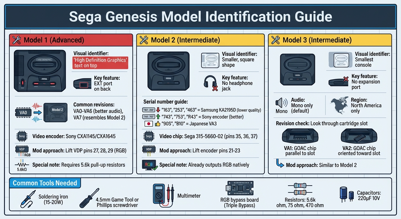
Sega Genesis Model Comparison Guide for RGB Modding
Identifying Your Console Model
Getting the right mod setup for your Sega Genesis starts with correctly identifying your console model. This step is crucial to ensure you use the appropriate components and methods for achieving optimal RGB performance. Make sure you know your Genesis model before making any modifications like cutting traces or soldering.
The Model 1 is the easiest to recognize. Look for the "High Definition Graphics" text on the top of the console and check the back for an EXT port. These features are typically found on earlier revisions (VA0–VA6), which are known for having better audio circuitry. If the AV out and power jack are closer to the center with a noticeable gap on the right side, you likely have the VA7 revision, which internally resembles the Model 2 architecture.
For the Model 2, its smaller, square shape and the absence of a headphone jack set it apart. Serial numbers can provide more details: units beginning with "163", "253", or "463" usually house a Samsung KA2195D encoder, which is known for lower-quality composite output. On the other hand, serials like "743", "753", or "R43" often indicate a Sony encoder (CXA1145 or CXA1645). Japanese VA3 consoles can be identified by serials starting with "90S" or "B10".
The Model 3 is the smallest and was a budget-friendly version sold only in North America. It lacks an expansion port and outputs mono audio by default. Without fully opening the console, you can identify the revision by peeking through the cartridge slot: VA1 GOAC chips are aligned parallel to the slot, while VA2 chips are oriented toward it.
Once you've determined your console model, the next step is to examine the motherboard for its specific revision and video encoder details.
Finding and Identifying the Motherboard
After identifying your console model, open the unit to locate the motherboard's key details. This step is essential for confirming compatibility with an RGB bypass board.
Using a Philips screwdriver or a 4.5 mm game tool, open your console and find the PCB revision number. These numbers are often printed near the edges or close to the cartridge slot. If you can’t locate a revision number, try checking the board part number instead (e.g., 837-7071 for VA3 or 171-6217 for VA7).
Next, identify the video encoder chip, such as the Sony CXA1145, CXA1645, Samsung KA2195D, or Fujitsu MB3514. This chip determines your motherboard's type and helps you select the right RGB bypass method. For Model 2 VA2 boards, look for "bodge" wires or an extra small PCB visible through the cartridge flaps - these are clear indicators. Additionally, powering on your console before disassembly can provide clues: if you see the "Produced by or under license from Sega" screen, you're dealing with a TMSS unit (VA6 or later).
RGB Modding Instructions
Now that you’ve identified your console and motherboard, it’s time to dive into the RGB bypass process. This modification requires precision soldering and results in permanent changes to your hardware. Work methodically, double-check every connection, and proceed carefully to achieve a clean and reliable RGB bypass.
Modding the Model 1
Begin by disassembling the console and removing the heat sink to access the motherboard. Locate the Video Display Processor (VDP) - commonly the Sega 315-5313 chip on VA3 boards. Using a small pick and heat, carefully lift the three RGB pins (Red: Pin 27, Green: Pin 28, Blue: Pin 29) from the VDP. This step isolates the RGB signal from the original circuitry but also removes the 5.6k pull-up resistors. To maintain proper color output, reinstall 5.6k pull-up resistors on the bypass board.
"Whenever you lift the pins or sever the traces, you should add the 5.6k pull-up resistors or it will change the curve of the colours significantly" - RetroRGB
Next, isolate the multi-out DIN from the internal encoder. Instead of cutting motherboard traces, cut pins 23 (Red), 22 (Green), 21 (Blue), and 11 (Csync) directly on the Sony CXA1145 encoder chip. Before making any cuts, verify these connections with a multimeter. Once isolated, solder the lifted VDP pins to the RGB bypass board inputs (such as a Triple Bypass). Then, connect the bypass board outputs to the corresponding pins on the multi-out DIN. After soldering, reduce noise by placing a capacitor between the 5V and ground pins near the RGB vias. Adding a second capacitor to pin 54 (sync) output can further eliminate "RAM noise."
For a simpler method to reduce jailbars without a full bypass, lift only the subcarrier pin on the VDP.
"Model 1 Genesis consoles are known for having really noisy RGB video output. One easy method of improving this, is simply lifting the subcarrier pin on the VDP" - RetroRGB
Keep in mind, lifting the subcarrier pin disables composite video output entirely.
Modding the Model 2
Unlike the Model 1, modding the Model 2 focuses on adjusting encoder connections rather than lifting VDP pins. Model 2 consoles already output RGB natively, but bypassing the internal circuitry eliminates jailbars and interference. Most VA1 boards use the Sega 315-5660-02 video chip, with RGB signals on pins 35, 36, and 37.
To begin, lift encoder pins 21–23 to disconnect the original RGB signals. For CSYNC, cut the multi-out trace instead of lifting the encoder pin to preserve composite video.
When installing a Triple Bypass on a VA0 revision, remove capacitors and resistors R62–R64. Then, bridge jumpers 2, C, D-Right, and E on the 3BP board before soldering it directly to the DIN pins.
"Make sure power is disconnected before proceeding" - ConsoleMods Wiki
"This mod should not be done by a beginner and is considered intermediate/advanced" - ConsoleMods Wiki
You may need to trim the bottom metal shield with snips to accommodate the added height of the bypass board.
If the screen appears dark after installation, your RGB cable likely contains 75-ohm resistors. In this case, remove the resistors from the bypass board and bridge the connections instead. After soldering, confirm there is no continuity between multi-out pins. Following these steps will greatly improve the RGB signal quality, delivering the kind of clarity you’re aiming for.
Testing, Troubleshooting, and Reassembly
Testing the Mod
Before putting the console back together, connect it to an RGB display using SCART or component cables. For the best results, use a PVM/BVM monitor or a modern HDTV with an upscaler like the OSSC or RetroTINK. Power on the console and load the 240p Test Suite to confirm the mod is functioning correctly.
"The 240p Test Suite... is my favorite go-to software for testing!!!" – RetroRGB
Head to the color gradient screen to check that each color step is clearly visible. On Model 1 consoles, if steps 6 and 7 seem to blend together, revisit the earlier instructions about resistor installation. If the image looks much darker than it should, you might be dealing with double termination - this happens when both the RGB cable and the bypass board have 75-ohm resistors.
"If you don't omit the 75Ω resistors on the board [when using a cable that has them], your video will be rather dark." – TMS-RGB
Before powering on, use a multimeter to test for continuity at your solder joints and ensure there are no shorts to ground or the 5V rail. For Model 1 consoles, also check that audio is coming through the front headphone jack unless you've modified it for internal stereo output.
Fixing Common Problems
If the display test shows problems, here are some common issues and how to address them:
- Dark image: This is usually caused by conflicting 75-ohm resistors on the bypass board and the RGB cable. Remove or bridge the resistors on the bypass board to fix this.
- Vertical "jailbars" or video noise: These are often due to subcarrier interference or aging filter components. Replacing the main filter capacitors can resolve this.
Here’s a quick reference table for troubleshooting:
| Symptom | Probable Cause | Suggested Action |
|---|---|---|
| Color gradient steps 6–7 blend | Missing 5.6k pull-up resistors | Install 5.6k pull-up resistors on the RGB lines |
| Image too dark | Double termination from resistors in both cable and mod | Remove or bridge the resistors on the bypass board |
| Vertical "jailbars" or persistent video noise | Subcarrier interference or aged filter components | Replace the main filter caps |
| Black screen with power LED on | Failing 7805 voltage regulator or shorted mainboard | Check RAM for overheating and verify the +5V rail |
| No audio or muffled sound | Leaky electrolytic capacitors | Replace the audio path capacitors as needed |
If the console powers on but displays a black screen, the issue could be a failing 7805 regulator or a shorted mainboard. Use a multimeter to check the +5V rail and probe the VDP/CPU reset line - it should briefly pulse low during power-on before stabilizing at 5V. After running the console for a couple of minutes, touch the main ICs; if any feel unusually hot, they’re likely shorted and need replacing. Also, check for simpler issues like dirty cartridge slots or AV ports - cleaning them with retro console cleaning kits might solve the problem.
These steps ensure your RGB mod delivers clean, high-quality video output.
Reassembling the Console
After confirming the mod works correctly, you can reassemble the console by following these steps:
- Route all new wires around the motherboard to avoid pinching them between components or the casing. Use tape to hold wires in place and prevent them from shifting.
- If an internal bypass board was installed, secure it near the multi-out port with double-sided tape to reduce stress on delicate solder points.
- Carefully place the metal shielding, ensuring it doesn’t crush or damage any wires connected to the bypass board or video pins.
- Inspect the board with a magnifier before closing the shell to confirm that no pins are shorted.
- As you lower the top cover, check for resistance - if the shell doesn’t sit flush, a wire might be caught between the plastic and the shielding.
- Power on the console one last time before tightening all screws. If it doesn’t boot, inspect the mod area for accidental shorts or lifted pins that weren’t properly re-seated.
Conclusion
RGB Modding Benefits
RGB modding dramatically improves both video and audio quality on Sega Genesis consoles. One of the most effective ways to eliminate those annoying vertical jailbars - common across all Genesis models - is through a full bypass. By installing a bypass board on Model 2 and 3 consoles, you can significantly reduce video noise and fix audio distortion, resulting in much cleaner sound.
This upgrade doesn’t stop at visuals and sound. By restoring accurate color curves with 5.6k pull-up resistors, RGB modding enhances color precision while also bypassing older, deteriorating components inside your console. If you own a Model 1 Genesis, modifying the multi-out port to use a Genesis 2–style DIN connector makes your cable setup simpler and improves compatibility with accessories like the 32X. These upgrades not only enhance your gaming experience but also help extend the life of your console.
Shop BJ's Game Vault for Retro Gaming Products

Once your mod is complete, take your retro gaming to the next level with top-notch titles and accessories from BJ's Game Vault. This is the perfect way to celebrate your upgraded console.
BJ's Game Vault offers a wide range of retro gaming products to complement your modded Genesis, including rare ROM hack cartridges, custom game cartridges, and reproduction titles for classic systems like the Sega Genesis, NES, SNES, N64, and GBA. Check out their full catalog at BJ's Game Vault and discover retro-tested products that make the most of your modded console.
FAQs
Do I need a Triple Bypass for my Genesis model?
A Triple Bypass mod is designed to elevate both audio and video quality by bypassing the system's internal circuits. However, it's worth noting that this mod isn't essential for basic RGB output. Most Genesis models, such as the Genesis 1, Genesis 2, and CDX, already support RGB when paired with the right cable. This modification is best suited for those seeking improved performance and who possess advanced soldering skills. For standard RGB functionality, a bypass modification isn't required.
Will an RGB mod break composite video output?
Performing an RGB mod on a Sega Genesis usually doesn’t interfere with the console’s composite video output. In fact, composite functionality often remains intact, particularly when employing techniques like an RGB bypass. That said, the final result can vary depending on the specific modding method applied.
Which RGB cable should I use after the mod?
For the best display quality, use an RGB SCART cable that matches your Sega Genesis model. If you're using a Genesis 2, a standard Genesis 2 RGB SCART cable will do the job. However, for a Genesis 1, you might need a specific cable or an adapter. Make sure the cable includes the required resistors and components to handle RGB output correctly - this is especially important if any internal modifications have been made to the console's circuitry.