


NESRGB Installation Guide
The NESRGB mod upgrades the video output of your front-loading NES from RF/composite to RGB and S-video, delivering sharper visuals with zero input lag. Created by Tim Worthington in 2013, the NESRGB bypasses parts of the NES's PPU to improve video quality and offers customizable color palettes. However, the installation is complex and requires advanced soldering skills, especially when removing the PPU chip from the motherboard.
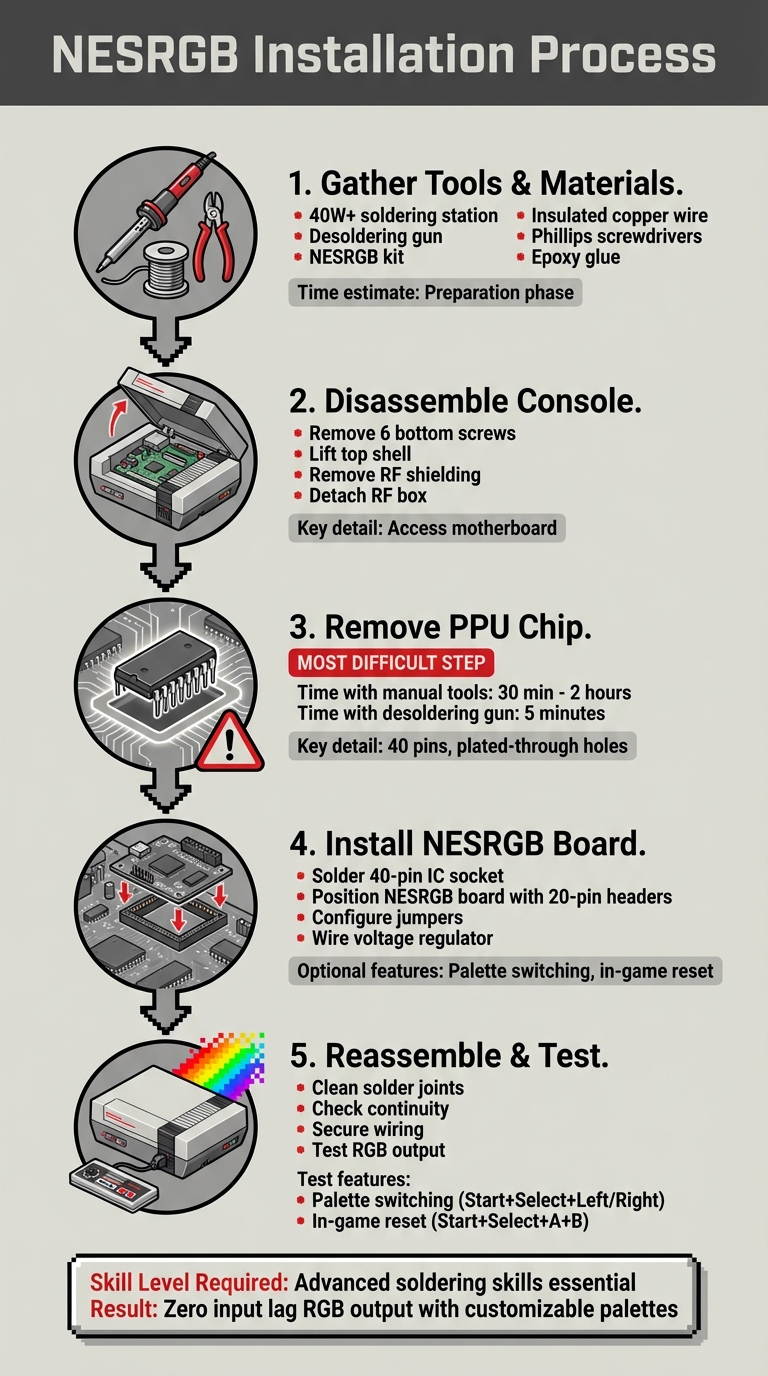
Key Steps:
- Disassemble the NES: Remove the RF shielding and RF box to access the motherboard.
- Remove the PPU Chip: Use a desoldering gun or soldering tools to safely extract the chip.
- Install the NESRGB Board: Solder the board into place, connect wires, and configure jumpers for your console type.
- Reassemble and Test: Verify the RGB output, palette switching, and optional features like in-game reset.
Tools and Materials:
- Soldering station (40-watt or higher)
- Desoldering gun or manual tools (solder sucker/wick)
- NESRGB kit (includes board, IC socket, connectors, and more)
- Insulated copper wire, Phillips screwdrivers, and epoxy glue
Testing:
After installation, ensure the RGB output works, test palette switching, and confirm all connections are stable. Proper tools and patience are essential for a successful installation.
This guide simplifies the process while emphasizing the technical skill required to transform your NES into a modern display-ready console.
NESRGB Installation Process: 5 Key Steps for NES RGB Mod
Installing NESRGB 4.1 and SNES Multi-out in an NES Frontloader, with in-game reset and a fancy case!
sbb-itb-9a4764e
Tools and Materials Needed
Before diving into the project, make sure you have all the necessary tools and components ready to protect both your console and the NESRGB board.
Required Tools
A 40-watt (or higher) soldering station with strong thermal capacity is critical. Tim Worthington highlights the impact of quality tools on installation time:
The efficacy of this method is dependent on the soldering iron chosen for the job. For example, it took me half an hour to remove the PPU with the 20+ year–old soldering station... With my high-performance Thermaltronics soldering station, I can remove the PPU in about five minutes.
For soldering, use 60/40 tin/lead solder to match the NES's original materials. A dedicated desoldering gun is also highly recommended to work efficiently and minimize risks. Brands like Hakko are well-regarded, but budget-friendly options like Aoyue or older Radio Shack models can also get the job done.
Other essential hand tools include Phillips head screwdrivers, wire cutters, wire strippers, and pliers. If you need to drill new ports, a step drill bit is ideal for creating clean 6mm (audio) and 12mm (video) holes. Additionally, keep isopropyl alcohol handy to clean solder joints and have two-part epoxy glue ready to secure video connectors.
Hardware Components
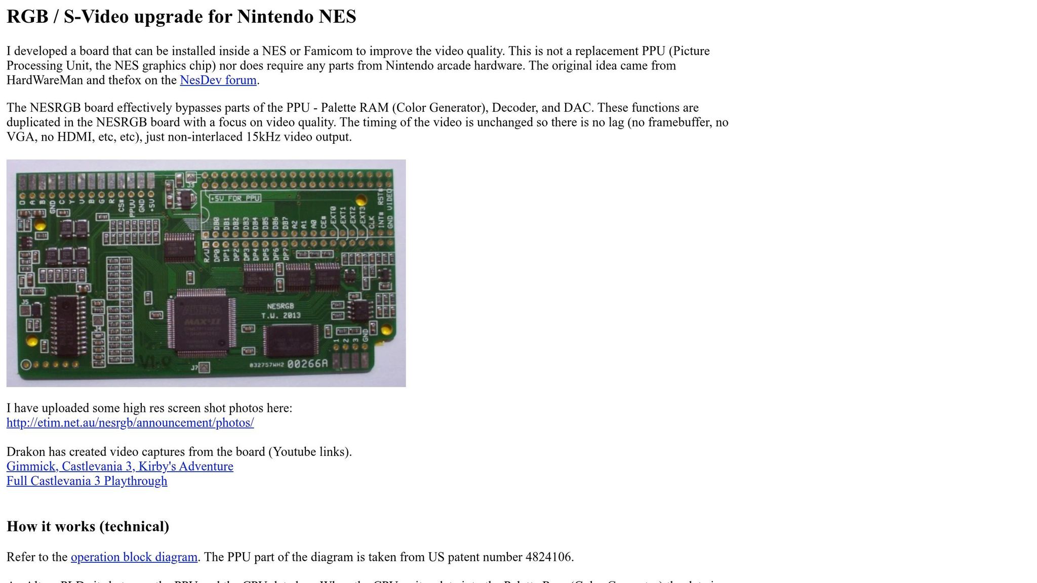
The NESRGB kit for front-loading consoles typically includes:
- Main board
- Voltage regulator board
- 40-pin DIP round pin IC socket
- Two 20-pin round pin header strips
- Palette selection toggle switch
The kit also provides video and audio connectors, including an 8-pin mini DIN RGB video connector, an S-video connector with pin label boards, and a 3.5mm audio jack socket.
For wiring, use insulated copper wire - thicker gauge for power and ground connections and thinner, more flexible wire for signals. Some installers opt for 3D-printed SNES-style Multiout AV ports from manufacturers like Laser Bear or Helder to preserve the original Nintendo aesthetic.
Lastly, while you're working on the console, it’s a good idea to replace the capacitors (similar to a SNES capacitor replacement). Use high-quality Japanese electrolytic capacitors from trusted brands like Nichicon, Panasonic, or Rubycon to ensure long-term reliability.
Once everything is set, you’re ready to start disassembling your NES console.
Disassembling the NES Console
Opening the Console
Start by flipping the NES console upside down. Remove the six Phillips screws on the bottom, then lift off the top shell to access the internal components. The first thing you'll see is the metal RF shielding that covers the motherboard. This shielding was primarily added to meet FCC regulations by reducing electromagnetic emissions. As TriMesh from ASSEMBLERgames explains:
Mostly the RF shielding is there for legal reasons - any digital device clocked at over 9kHz sold in the US has to be certified to comply with the FCC emission limits. Removing the shielding will likely make it theoretically non-compliant, but is unlikely to hurt anything.
In most cases, removing this shield is safe, though in environments with high electromagnetic noise, you might notice slight interference. Use a Phillips screwdriver to remove the screws holding the RF shield in place, then carefully set it aside. Once the shield is removed, you'll have full access to the motherboard, allowing you to move on to detaching the RF box.
Removing the RF Box
The RF box is located at the rear of the console and handles power input and filtering, which includes a prominent electrolytic capacitor. To remove it, flip the motherboard over to expose the four large metal tabs that secure the RF box to the board. Before desoldering, pre-tin each tab to improve heat conduction. Once pre-tinned, use a solder pump or wick to clear the solder. Wiggle each tab gently to ensure they are free, then remove the RF box.
If you plan to use the rear ports for other purposes, keep in mind that the power circuit components within the RF box are essential for the console to function. You'll need to either retain or replace these components. With the RF box removed, you'll now have access to the internal components, readying the console for the PPU removal process. If you prefer professional assistance, you can explore RGB modding services for NES consoles to handle the installation for you.
Removing the PPU Chip
The Picture Processing Unit (PPU) is the component you’ll need to remove to install the NESRGB board. On NTSC consoles, this chip is labeled RP2C02, while PAL systems use the RP2C07. This step is particularly tricky because the NES motherboard uses double-sided, plated-through holes with copper plating, creating very strong solder joints. Proper removal of the PPU is crucial for a successful NESRGB installation. Tim Worthington, the NESRGB creator, explains:
Removing the PPU is the most difficult part of the installation. If you have access to a desoldering iron, I recommend using it instead as it is by far the easiest way to remove ICs from plated-through boards.
Desoldering the PPU
Begin by applying fresh 60/40 tin/lead solder to all 40 pins on the bottom side of the board. This step is important as it improves heat transfer and makes the old solder easier to remove. Flip the board and use solder wick to remove solder from the top pins. Then, return to the bottom side and use a solder sucker to extract the remaining solder.
Worthington highlights specific trouble spots:
Pins 14–17 and pin 20 are usually the most difficult because they are often connected to a ground plane. This acts as a heat sink and makes it difficult to heat the joint.
For these challenging pins, add more solder, apply heat evenly, and gently lift the PPU while the solder remains molten. Before attempting to remove the chip, use tweezers to wiggle each pin to ensure they move freely. Worthington advises:
Only attempt to lift the PPU from the board once all IC pins can move freely in the holes.
Using traditional tools, this process typically takes between 30 minutes and 2 hours. However, the quality of your soldering iron can significantly affect the time required. Worthington shares his experience:
The efficacy of this method is dependant on the soldering iron chosen for the job. For example, it took me half an hour to remove the PPU with the 20+ year-old soldering station... With my high-performance Thermaltronics soldering station, I can remove the PPU in about five minutes.
If you’re looking for a faster option, consider using a desoldering gun.
Using a Desoldering Gun
A professional desoldering gun, such as those from Hakko or Aoyue, offers the quickest and safest way to remove the PPU. These tools can reduce the removal time to just 5 minutes compared to the 30 minutes to 2 hours required with traditional tools. While manual solder suckers are more affordable, professional desoldering guns save time and minimize the risk of damaging the board. If you plan to perform multiple NESRGB installations or other console modifications, investing in a desoldering gun can be a smart choice. After removing the PPU, use a hot soldering iron to clean any residual solder burrs from the pins before inserting it into the NESRGB board.
Installing the NESRGB Board
With the PPU removed as described earlier, the next step is installing the NESRGB board. Begin by soldering a 40-pin DIP round pin IC socket into the NES motherboard where the PPU used to be. This socket will hold the NESRGB board securely in place.
Positioning the NESRGB Board
To ensure proper alignment, first insert the two 20-pin round pin header strips into the socket on the motherboard. Then, place the NESRGB board on top of these headers and solder the pins to the board. The socket serves as a guide to keep everything aligned vertically. The PPU chip itself must be soldered directly onto the NESRGB board - a socket cannot be used here due to height limitations inside the console. Be sure to double-check the orientation of the PPU before soldering to avoid any mistakes.
On many NES motherboard revisions, you’ll find two blue electrolytic capacitors near the PPU socket that can obstruct the NESRGB board. To resolve this, heat the solder joints on these capacitors and carefully tilt them so they lie flush with the motherboard. This adjustment ensures the board can sit properly.
Soldering the Board
Prepare wires for internal connections by cutting and tinning them to approximately 250mm. Use thicker gauge insulated copper wires for power and ground connections to maintain stable operation.
Set the solder jumpers according to your console type. For NTSC front-loaders, close jumper J10 to enable de-jitter, close J6 for positive reset polarity, and replace the 100n ceramic capacitor (C8) with the supplied 220n capacitor if you're using NESRGB v4.
Install the separate voltage regulator board included in the kit. The original NES regulator heatsink may overheat due to the additional power demand. For video output, wire the connector using the labeled pin boards provided in the kit. If you're using SCART systems, connect composite video (V) for sync to ensure compatibility in case RGB output becomes unavailable.
Once the primary connections are complete, you can move on to setting up optional features to expand the board's functionality.
Adding Optional Features
The NESRGB board allows for controller-based palette switching. To enable this, close jumper J1 and wire the Data, Clock, and Latch signals (pads 1D, 2C, 3L) to the Player 1 controller port. This feature lets you switch palettes during gameplay by pressing Start+Select+Left/Right.
For in-game reset, connect the "RO" pad on the board to the console's reset signal. This enables a reset function using Start+Select+A+B during gameplay.
Jumper J9 is used to control the THS7374 Low-Pass Filter. Leaving it open provides a sharper image, while closing it softens the image and reduces electromagnetic interference. For sync output, jumper J8 determines the type of sync: open for TTL sync or closed for 75-ohm composite sync. The 75-ohm setting is generally safer to prevent damage to video receivers. If you want to separate audio from video to eliminate buzzing noises caused by low-quality SCART cables, install a dedicated 3.5mm audio jack.
Reassembling and Testing
Cleaning the Solder Joints
Before sealing the console, take a moment to clean up the soldering work. Heat each PPU pin with your soldering iron to smooth out solder burrs, and use tweezers to clear away any stray solder fragments. Then, set your multimeter to continuity mode and test the connection between PPU pin 24 (/RD) and pin 20 (OE) on the VRAM, as well as pin 21 on the cartridge connector. A successful connection will trigger the multimeter's beep, confirming continuity.
Inspect the area around the PPU socket for lifted pads, which can happen if the original PPU was removed without specialized desoldering tools. If you spot any lifted pads or broken traces, you’ll need to use a "bodge wire" to manually reconnect the points based on the console's schematic.
Putting the Console Back Together
Once you're confident in the integrity of the solder joints, it's time to reassemble the console. Make sure the blue capacitors near the PPU socket are seated flush against the motherboard. Use hot glue to secure internal wiring, keeping it stable and out of the way during assembly. Double-check that the solid ground wire connects the NESRGB board to the output ground point on the Power/Audio board - this step is crucial for minimizing power supply noise that can interfere with video quality.
Reinstall the motherboard using the original Phillips head screws. If you added a 3.5mm audio jack to the 6mm hole you drilled earlier, ensure the hole is recessed properly. Keep in mind that the NES casing is about 3mm thick, while the jack is designed for 2mm panels. For the video connector installed in the 12mm hole, confirm that the two-part epoxy has fully set and that the connector board is positioned correctly, with the pin label board showing the circle on the correct side.
Testing RGB Output
After reassembly, it's time to test the system. Connect your RGB cable to the video output, and if the cable's plug doesn’t fully insert, trim its plastic casing to ensure a proper fit. Power on the console with a game cartridge inserted and check for a clear RGB video signal.
Test the palette switching system by using your controller. Press Start+Select+Left or Start+Select+Right to switch palettes, or hold Start+Select+Left for 2 seconds to toggle the NESRGB board on or off. If you wired the reset connection, confirm the in-game reset works by pressing Start+Select+A+B.
For NESRGB version 4 boards, check the onboard LEDs (0–7) to confirm everything is functioning as expected. LED 7 serves as a warning indicator and will blink if there’s an issue with the power-up reset circuit. If you notice an "open bus" pattern on the screen, which appears as repeating graphical glitches, reflow the suspect solder joints with additional solder to ensure a solid connection. Lastly, verify the audio output through the 3.5mm jack. When no cable is plugged into the jack, the audio should automatically route to the 8-pin mini-DIN RGB connector.
Conclusion
Installation Summary
Installing the NESRGB board can breathe new life into your front-loading NES by delivering sharp RGB video output. The process starts with removing the PPU chip from the motherboard. Once removed, you’ll need to install a 40-pin IC socket in its place, solder the NESRGB board with its pin headers, and adjust the solder jumpers based on your console’s region and desired features.
Key steps include wiring the voltage regulator, setting up the palette switching feature (available through the controller port on version 4 boards), and ensuring a stable ground connection. After reassembling the console, test the palette switching commands and in-game reset functionality to verify the installation was successful. While first-time installers may need a few hours to complete the process, the payoff is clear: better video quality and a refreshed NES experience on modern screens.
Where to Find Components
Once your installation is complete, consider sourcing additional components for future upgrades. Tim Worthington, the NESRGB board’s creator, offers official installation kits that include the board, palette selection switches, audio jacks, S-video and RGB connectors, and IC sockets. For version 4.0 and newer boards, features like controller-based palette switching and built-in de-jitter circuits are included.
BJ's Game Vault is another great resource for retro gaming enthusiasts. They carry a variety of products to elevate your modded console, including custom cartridges, reproduction vintage games, gaming accessories, and fan-made creations. With these components and games, you’ll be fully equipped to enjoy your upgraded NES to the fullest.
FAQs
Is NESRGB only for front-loading NES models?
NESRGB works seamlessly with both front-loading and top-loading NES consoles, as well as the Famicom and AV Famicom. It upgrades the video output on these systems by providing RGB and S-video outputs, user-selectable palettes, and built-in audio/video amplifiers. Plus, it’s compatible with both NTSC and PAL systems, making it a flexible solution for different NES and Famicom models.
What’s the safest way to remove the PPU without lifting pads?
To safely remove the PPU without damaging the pads, you'll need tools like a solder wick and a solder sucker. Start by using the solder wick to absorb the solder from the PPU's pins on the top side of the board. Once that's done, use the solder sucker to clear out any remaining solder from the bottom side. Work carefully to avoid overheating the board or applying too much force, as both can harm the pads or the board itself.
Which jumpers should I set for NTSC vs. PAL consoles?
The NESRGB board is compatible with both NTSC and PAL systems. However, the articles don't specify the exact jumper settings for each region. To ensure proper configuration, refer to the NESRGB documentation or the installation guide tailored to your console's region. The instructions primarily cover general setup rather than region-specific jumper settings.