


How to Avoid SNES Damage During RGB Mods
Modding your SNES for RGB output can significantly improve video quality, but it comes with risks. To avoid damaging your console, follow these key tips:
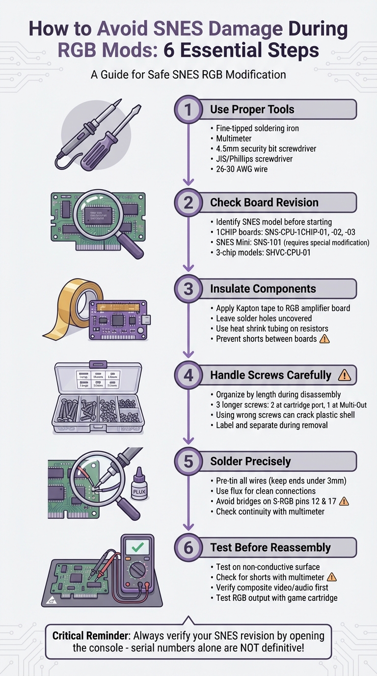
- Use Proper Tools: A fine-tipped soldering iron, multimeter, and correct screwdrivers (4.5mm security bit and JIS/Phillips) are essential.
- Insulate Components: Apply Kapton or electrical tape to prevent shorts between the RGB amplifier board and the motherboard.
- Check Your Board Revision: Identify your SNES model to ensure compatibility and avoid incorrect modifications. This includes ensuring you choose the correct power cables to prevent electrical damage after the mod is complete.
- Handle Screws Carefully: Organize screws by length during disassembly to prevent cracking the plastic shell during reassembly.
- Solder Precisely: Avoid solder bridges, especially on tightly spaced S-RGB chip pins, by using flux and pre-tinning wires.
- Test Before Reassembly: Use a multimeter to check for shorts and confirm RGB output works properly.
SNES RGB Mod Safety Checklist: 6 Steps to Avoid Console Damage
Tools and Preparation
Required Tools and Materials
To get started, you'll need a few specific tools. First, have a 4.5mm security bit screwdriver ready to remove the four screws securing the external shell. Once the shell is off, switch to a Phillips screwdriver or, ideally, a JIS screwdriver to remove the seven internal screws that hold the PCB and RF shield in place.
For the soldering work, use a soldering iron with a fine tip for precision when working on the S‑RGB or S‑CPUN chip pins. Thin leaded solder with plenty of flux will ensure smooth solder flow onto the tiny PCB pads while avoiding solder bridges. You'll also need 26–30 AWG wire to route signals from the chip to the Multi‑Out port. Keep a multimeter handy to check continuity and spot any accidental solder bridges.
To protect your workspace and the console, use Kapton tape or electrical tape to insulate the mod board from the motherboard. Before starting, clean the board using isopropyl alcohol and cotton swabs to remove dust and old flux. Once you've soldered, trim any excess wire leads with flush cutters to prevent contact with other components or the console shell. To stay organized, store screws in a small container - note that the screws near the cartridge port and Multi‑Out port are longer. Using these in the wrong spots could crack the bottom shell.
With everything in place, confirm your SNES board revision before moving forward.
Checking Your SNES Board Revision
To identify your SNES board revision, examine the text printed on the PCB. This step is crucial for ensuring safe disassembly and accurate soldering.
If your console has a 1CHIP board (labeled SNS-CPU-1CHIP-01, -02, or -03), you're in luck - these offer the sharpest RGB output. However, brightness adjustments are necessary, requiring 750‑ohm resistors. Keep in mind, the 1CHIP‑03 revision lacks CSYNC on the Multi‑Out port, so you'll need a Sync‑on‑Luma cable or a modification to restore proper signal output.
For SNES Mini systems (SNS‑101/SNES Jr.), native RGB output isn't available. In these cases, you'll need to solder directly to pins 18, 20, 22, and 24 on the S‑RGB chip and add 1.2k‑ohm pulldown resistors. Older 3‑chip models like the SHVC‑CPU‑01 have separate CPU and PPU chips. Depending on the sub-revision, this may involve removing certain transistors or resistors. While the console is open, inspect SHVC‑CPU‑01 boards for leaky capacitors, as these components are prone to failure over time.
sbb-itb-9a4764e
How to Disassemble Your SNES Safely
Disassembly Steps
Start by unplugging the power cable and setting the power switch to "on." This step ensures any residual charge in the capacitors is safely discharged.
Flip the console over to locate the 4.5mm security screws on the bottom shell. Depending on your model, you'll find four screws on the SNES Jr. or six screws on the standard and PAL models. Use a security bit screwdriver to remove these screws. Once they're fully loosened, the case should lift off easily. If it doesn’t, double-check for any screws you might have missed - never force the case open.
With the top shell removed, you’ll see the power switch and eject mechanism. To remove the power switch, unscrew the Phillips screws and unplug the plastic socket carefully (avoid pulling on the wires). For the eject mechanism, keep a finger on the small spring under tension to prevent it from popping out while you lift the metal rod.
Next, disconnect the front panel ribbon cable by gently pulling on the plastic connector - not the cable itself. Remove the Phillips screws holding the RF shield in place, then lift the shield carefully to avoid bending its metal prongs. Finally, unscrew the five to seven Phillips screws securing the motherboard to the bottom shell. Pay close attention to the three longer silver screws near the cartridge port and Multi-Out port - set them aside separately. Using these screws in the wrong spots during reassembly could damage the bottom shell.
Before moving on, clean the interior using a retro console cleaning kit. Use compressed air to blow out dust and cotton swabs dipped in isopropyl alcohol to wipe down the PCB and connectors. This step helps eliminate grime and old flux that could interfere with soldering or reduce video quality.
Once your SNES is disassembled and cleaned, you’re ready to install the RGB mod. Be precise with your soldering techniques to avoid damaging components.
Mistakes to Avoid During Disassembly
Avoid these common errors to keep your SNES intact during the process.
One of the most frequent mistakes is mixing up screw lengths. The ConsoleMods Wiki highlights this issue:
"Note that the two screws on each side of the cartridge port and the one on the multiout are longer than the rest. Do not use these anywhere else or damage to the bottom shell may result."
To prevent confusion, store and label all screws - especially the longer ones from the cartridge and Multi-Out ports - separately.
Another common misstep is pulling on wires instead of the connectors. As iFixit contributor Arty Boomshaka advises:
"Don't pull on the wires to avoid damaging them. Pull on the plastic socket instead."
Lastly, forcing parts apart can lead to cracked solder joints or broken plastic clips. If something won’t budge, check again for any missed screws or connections before applying force. These small precautions can save you a lot of trouble.
Soldering and Installing the RGB Mod
Protecting Components with Insulation
Before diving into soldering, it's crucial to insulate the RGB amplifier board to avoid electrical shorts. Use Kapton tape on the bottom side of the amplifier, but leave the solder holes uncovered. This precaution ensures the amplifier doesn’t come into contact with the SNES mainboard, which could otherwise result in short circuits.
For components like resistors used in brightness adjustments, wrap them in heat shrink tubing. This step prevents accidental contact with other parts of the board. After soldering, secure any loose wires with additional Kapton tape. This keeps them in place and prevents them from shifting or getting pinched during reassembly of the console shell and heat shield. Once everything is insulated and secure, you’re ready to move on to the soldering process.
Proper Soldering Techniques
With insulation out of the way, it’s time to focus on precise soldering. Start by tinning all connection points before making final solder joints. Tinning involves melting a small amount of solder onto the tip of a wire, making it easier to attach to a solder pad with just heat.
Keep pre-tinned wire ends short - no more than 3mm. This minimizes the risk of exposed conductors touching nearby components and causing shorts. If you’re having trouble getting solder to stick to PCB pads, apply some soldering flux. It helps create cleaner and more reliable connections.
When working with the S-RGB chip, be extra cautious around pins 12 and 17. As Michael Iantorno notes:
"The S-RGB Chip's pins are very close together. Make sure that you do not accidentally bridge the neighbouring pins."
After soldering, use a multimeter to check continuity and confirm there are no unwanted bridges between these pins before powering up the system.
Desoldering Methods Compared
If you need to fix mistakes or prepare components, choosing the right desoldering method is essential. Here’s a comparison of the most common techniques:
| Method | Pros | Cons | Best Use Case |
|---|---|---|---|
| Solder Pump / Wick | Great for clearing through-holes and removing bridges | Wick can stick if not heated enough; pump requires steady handling | Cleaning multi-out pins or fixing solder bridges between S-RGB pins |
| Flush Cutters | Cuts excess component legs cleanly and flush | Can damage the PCB if the tool slips | Removing the two protruding pins on the SNES PCB for a flush RGB amp fit |
| Component Stacking | Avoids desoldering surface-mount components | Can appear cluttered; requires a steady hand | Adding a 220nF capacitor to C11 to reduce video ghosting |
For delicate fixes, such as reducing video ghosting, stack a new 220nF capacitor directly on the existing C11 capacitor. This approach avoids the risk of damaging PCB pads that could occur during desoldering.
Reassembly and Testing
How to Reassemble Your SNES
Once you're done with soldering and have secured all components, it's time to put your SNES back together.
Start by sorting the screws based on their length. The SNES motherboard requires seven Phillips-head screws, but they aren't all the same size. Three longer screws are meant for specific spots: two on either side of the cartridge port and one at the multiout port.
Before securing the motherboard, reinstall the 7805 voltage regulator heatsink. Attach the heatsink to the motherboard first, using the two screws with spiked washers, then fasten the 7805 regulator to the heatsink. If you routed wires near the heatsink earlier, make sure to wrap it with electrical tape to prevent any accidental shorts.
Double-check that all wires are correctly routed. They should either pass through cleared vias or be positioned under the heatsink in a way that avoids being crushed during reassembly . If you've installed larger capacitors, gently bend them upward to ensure they clear the rear casing.
Testing the Mod
Before fully closing up the console, ensure that all your modifications are functioning properly.
Start by testing the motherboard on a non-conductive surface, such as a towel or foam mat, to avoid any accidental damage. Turn the power switch to "on" while the console is unplugged - this will discharge the capacitors and safely de-energize the system.
Next, use a multimeter to check for shorts between the newly soldered RGB and sync points and ground. Inspect each solder joint visually to ensure there are no bridges or cold joints (cold joints often look dull or grainy). If you're using a TTL C-Sync cable, confirm that the TTL jumper on your bypass board is properly bridged with solder.
To test the hardware, insert a game cartridge and power on the console. If you need to expand your library, you can find retro games and accessories to ensure your system is fully compatible with various titles. Start by checking basic composite video and audio to make sure the core system is still working. Then, connect your RGB cable to test the image quality. If the picture looks too bright or washed out, you may need to add 1.2k ohm pulldown resistors to adjust brightness levels. If you notice ghosting or ringing on solid backgrounds, consider replacing capacitor C11 with one rated between 220nF and 470nF .
Once you've confirmed that everything is working as it should, reassemble the outer shell. Use the correct screws in their designated spots, and for the outer casing, you'll need a 4.5mm gamebit screwdriver .
SNES Mini RGB Modification - Install Overview & Demonstration
Conclusion
Modding your SNES for RGB output takes preparation, the right tools, and careful execution. As modder Voultar wisely advises:
"You MUST disassemble your console to verify your SNES revision! The serial number alone is NOT definitive!"
This serves as a critical reminder - double-check everything before you start soldering. Assumptions can lead to mistakes, so verifying your console's revision is non-negotiable.
The most frequent issues during modding are entirely avoidable. Problems like solder bridges on tightly spaced pins, shorts caused by uninsulated components, or errors during reassembly (like mismatched screws) can all be prevented with a little extra care. Insulating your amplifier board with Kapton tape, keeping screws organized, and using a steady hand with a fine-tipped soldering iron are small but essential steps that make a big difference.
Testing is another crucial step. Before reassembling the console, use a multimeter to check for shorts and confirm that both composite and RGB outputs are functioning as expected. A quick test at this stage can save you from having to reopen the console later.
Once your mod is complete, consider investing in high-quality tools and parts for future projects. If you're interested in similar upgrades for other systems, you can also explore RGB modding services for NES consoles. If you're looking for reliable retro gaming supplies and accessories, check out BJ's Game Vault.
With patience, attention to detail, and the right equipment, you can successfully complete your SNES RGB mod and enjoy a beautifully enhanced gaming experience.
FAQs
How do I quickly confirm my SNES board revision?
To figure out your SNES board revision, start by locating the motherboard model number and serial number. These are typically printed on the board itself or inside the console. Some of the well-known revisions include SHVC-CPU-01, SNS-CPU-RGB-01, and SNS-CPU-1CHIP-01. For instance, if you see SNS-CPU-1CHIP-01, you're looking at a 1CHIP revision, which dates back to around 1995. The quickest way to determine your revision is by checking the serial number or opening up the console for a closer look.
What’s the safest way to avoid shorts after installing an RGB amp?
When installing an RGB amp on your SNES, taking the right precautions can save you from frustrating shorts and potential damage. Here are some key steps to keep in mind:
- Trim components carefully: Make sure to trim capacitor legs and other components neatly. This helps prevent accidental bridging between connections.
- Use the right tools: Equip yourself with a 4.5mm gamebit screwdriver for opening the console and a reliable soldering iron for precise work.
- Inspect and solder with care: Double-check all connections before powering up. Avoid using too much solder or applying excessive heat, as both can lead to issues.
Before putting everything back together, test your console to ensure the installation is successful. This small step can save you a lot of hassle down the line.
What should I check first if RGB looks too bright or has ghosting?
If the RGB output appears overly bright, start by checking and adjusting the brightness level. For SNES 1CHIP consoles, you can address this by soldering three 750 Ohm resistors or swapping out resistor R3 with a resistor rated between 1.84 kOhm and 1.87 kOhm.
If you notice ghosting on the display, replacing capacitor C11 with either a 470 nF or 220 nF capacitor should fix the problem. Always prioritize adjusting the brightness before tackling ghosting issues.